CLICK HERE TO BUY NOW FOR NON-ATTA FUEL TANKS.
Note: If you have a ATTA made fuel tank, please call us at 1-800-773-3047 with your Model Number and Serial Number to receive a lower price.
How It Works
Whenever the truck ignition is on, you press and hold the momentary switch in the on position. With the switch depressed the inline fuel pump is activated and will begin to transfer fuel from the auxiliary tank to the factory tank. When you let go of the switch, the pump is turned off. The auxiliary gauge reads what is in the auxiliary tank. The factory gauge reads what is in the factory tank.
Do not press the momentary switch for more than 5 minutes, and allow ten minutes between reactivating the switch. This will allow the factory gauge to give a more accurate reading of the factory tank. Do not activate the momentary switch if the factory tank is above 3/4 of a tank. Failure to do so can result in over-filling/over-pressurization of the factory. Do not activate the momentary switch if the auxiliary tank is empty.
Installation Kit Includes:
- 1x Auxiliary 2 1/16” Fuel Gauge
- 1x Auxiliary Tank Momentary Switch
- 1x Fuel Gauge &amli; Momentary Switch Wiring Harness
- 1x Auxiliary Tank Sending Unit
- 1x Sending Unit Harness
- 8’ of 3/8” & 5/16” Fuel Hose (for supply & return)
- 3’ of 5/16” Fuel Hose &nbsli;
- 1x Vent-Line Adaptor
- 1x Rotary Vain Fuel Pump w/ applicable hardware (70 Gallon Per Hour)
- Applicable wire connectors, nuts & bolts, self tapping screws
- NOW COMES STANDARD WITH GAUGE & SWITCH POD
Push 'n' Fuel Installation Instructions
WARNING: Read complete instructions before installation. Do not alter or substitute any part or component that is provided in installation kit. Failure to follow instructions and use of approved components will void warranty and may not meet D.O.T. regulations.
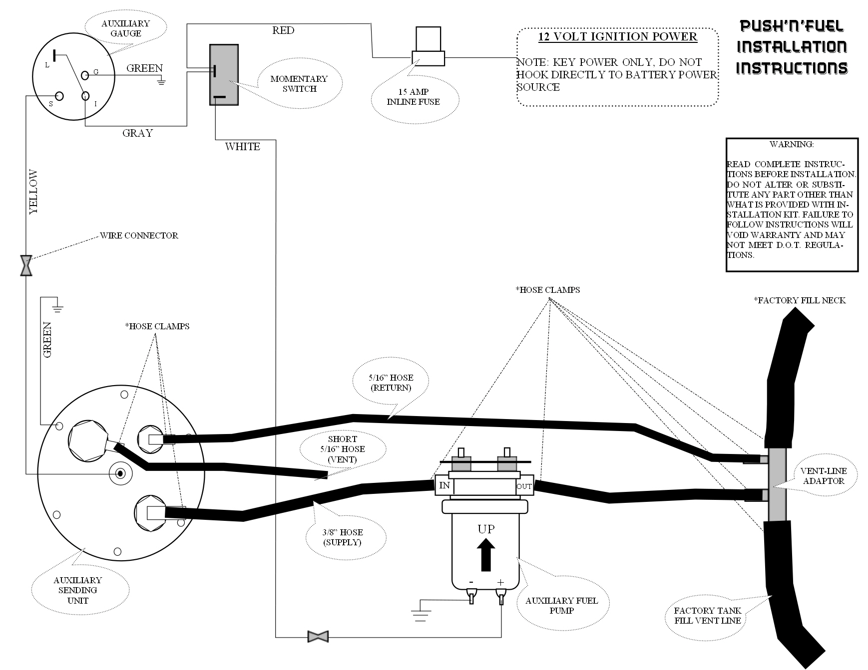
- Mount auxiliary fuel gauge and momentary switch in desired location within truck cab. NOTE: It may be necessary to remove wire connectors from momentary switch to mount and run wires between gauge and switch. Ensure connections are replaced to the same location on momentary switch.
- WARNING: Connect power source to 12 volt ignition power source only. Do not connect to battery power source.
- 2. See owner’s manual for location of either a spare fuse or upfitter fuse. Connect the RED wire from the switch to a 12 volt ignition power source. Note: Spare & Upfitter fuses are not used in any factory system and should be used when adding any accessory part. To add the 15 amp inline fuse to the red wire, cut the red wire and place one end of the wire inside the fuse holder and clamp that side down. Place the other side of the wire to the other side of the fuse holder and clamp down. Insure each side of the fuse holder is properly in the locked position.Insert the 15 amp fuse to the fuse holder at the end of the installation.
- Connect the GREEN wire from the auxiliary gauge to Chassis ground. This can be done by attaching a small eyelet to the wire using a self tapping screw to a chassis ground. NOTE: Chassis ground is metal to metal contact.
- Route the WHITE and YELLOW wires through the fire wall and route the wires along the frame rail. Insure the wires do not come into contact with any moving parts or exhaust lines. Use a small grommet or rubber boot when routing wires through the fire wall to insure the wires will not chaff or create a short.
- Apply the gasket sealer (Hylomar) to both sides of the gasket of the sending unit. Note: One packet of Hylomar per side of gasket. Install the Sending Unit Assembly to the tank using self-tapping screws. DO NOT BEND FLOAT ARM WHEN INSTALLING SENDING UNIT INTO THE TANK. Attach the sending unit harness to the tank. The YELLOW wire attaches to the center post of the auxiliary sending unit and will connect to the yellow wire from the auxiliary gauge. The GREEN wire from the auxiliary tank needs to be connected to Chassis Ground.
- Connect the 3/8” hose to the 3/8” supply port on the Sending Unit using a hose clamp. Connect the long 5/16” hose to the 5/16” return port (plastic) using a hose clamp. Connect the short 5/16” hose to the 5/16” vent port (metal) using a hose clamp. Tighten all hose clamps to insure proper seal.
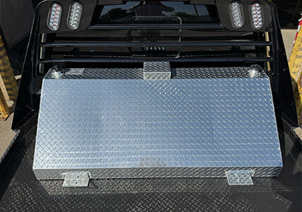
- Remove the Lock-Bar from the auxiliary tank and throw away shipping screws. Drill a 3/8” hole approximately 2” from each end of the Lock-Bar and place a bolt in each hole. Ensure the upper portion of the ‘L’ of the lock bar is up against the tank, like it was shipped. Position and center the auxiliary tank in the truck bed. Insure the auxiliary tank is placed on some sort of isolation mat. (Drop-In or Spray-In bed liners will work. Mud Flaps or a rubber mat will work also). The front hold-down tabs of the tanks will slide under the lock-bar. Drill the rear hold-down(s) of the tank and place a bolt in the hole. Route the wires and hoses under the truck. Insure the hoses are properly tied and no sharp bend was created. Place one flat washer, one lock washer and one nut on each bolt. Tighten all bolts. NOTE: Hauler/flatbed tanks do not have a lock-bar, just drill directly through hold-down tabs.
- Locate the factory fill neck on the inboard side of the truck bed. If it is a 5/8” vent line, place it upon the 5/8” portion of the Vent-Line Adapter. If it is a 3/4" vent line, place it upon the 3/4" Vent-Line Adapter. Mark the vent line where the cut should be made. Insure you will have enough hose to slide over the adapter. Cut a small section of either the 5/8” or 3/4” vent line. Place a large hose clamp on each side of the cut section. Insert the Vent-Line Adapter with the 5/16” hose port toward factory fill neck and the 3/8” hose port toward factory tank. Tighten the hose clamps. NOTE: Some trucks have internal vent lines and will require special push-in adaptors not provided in kit.
- WARNING: This pump is equipped with dry-seal fuel fittings. Do not use Teflon tape or pipe sealant on pipe fittings, or pump breakage will occur. This will void warranty.
- Mount inline fuel pump near the Vent-Line Adaptor, ensuring the fuel flow is going from auxiliary tank to factory tank. (IN from auxiliary tank-OUT to factory tank). Mount fuel pump mounting bracket on truck frame, ensuring fuel pump will be mounted with the arrow in upwards position. Attach 3x rubber grommets to mounting bracket top holes for placement of fuel pump. Push fuel pump mounts through rubber grommets and connect with flat washer, lock washer, and nut. Tighten all nuts.
- Run the 3/8” supply hose & the 5/16” return hose from the auxiliary tank to the Vent-Line Adapter area. Attach the 3/8” supply hose to the inline pump. Place and tighten with a hose clamp. It will be necessary to cut the excess hose off. Attach the remaining portion of the 3/8” hose to the other side of the pump. Place and tighten with a hose clamp. Route the 3/8” hose to the Vent-Line Adapter and place upon the 3/8” port. Route the 5/16” hose to the Vent Line Adapter. Place and tighten with a hose clamp.
- The push-on terminal wire for the fuel pump with pre-attached eyelet is connected to the (-) negative terminal of the fuel pump. The negative terminal is for chassis ground and may be connected to the mounting bracket/chassis frame bolt. The push-on terminal wire without attached eyelet is connected to the (+) positive terminal of the fuel pump. The positive terminal connects to the WHITE wire from the momentary switch. Be sure the terminal wires are properly and securely seated on fuel pump terminals.
- NOTE: Use proper safety precautions and procedures when dealing with any fuel or electrical components
WARNING: Read complete instructions before installation. Do not alter or substitute any part or component that is provided in installation kit. Failure to follow instructions and use of approved components will void warranty and may not meet D.O.T. regulations.


